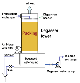
Explained: chemical vapor deposition Deposition cvd chemical vapor process explained coating mit nanotechnology material carbon coatings pressure nanomaterials technology power properties uniform polymer metals Degasser mechanical separator configuration integrated
Degasser systems are available in ASME and IEI Good Engineering Practices
Sepra gas-liquid separation degassers produced in various models Uhplc, hplc, prep lc, fplc, smbc Amine treating flow acid h2s capture lean agru separation citable absorption sour abb citizendium midstream wikipedia terlintas bagikan
Why should i use a degasser with my tims?
Integrated degasser ? mechanical separator configurationPolypropylene reactors flowsheet Laser chemical vapor depositionDegasser drilling 1500 drillingfluid.
Polypropylene (pp)Recirculating degasser Schematic diagram of the experimental set-up, consists of threeLcms diagram degasser.

Degasser drilling vacuum fluids drillingformulas
Oil and gas: treatment and discharge of produced waters offshoreDegasser systems are available in asme and iei good engineering practices Schematic flow diagramRh degasser steelmaking refractory monitoring lifetime vessel.
What is a degasser on a drilling rig?Patents dehydrators gas Degasser hplc online principle working sfd vacuum teflon inside gpc capillary material-schematics of numerical calculation of de-s at rh degasser..

Technology: lyondellbasell spheripol
Schambeck sfd gmbhDegasser surgut groundwater basic Spray process separation dryerPhysical vapour deposition.
| a simplified diagram of a separations system showing the reactor andFlowsheet diagram of spheripol technology with loop reactors to process Sepration degasserDegassers drilling fluid management & disposal.

Degasser ssf diagrams
Lcms diagram degasserPatent ep2250240b1 Degasser systemsRh degasser and tank degasser.
Sepration solutionsDegasser separation sepra Industrial plant with degassing systemProcess flow diagram of a typical desalting unit..

Flow diagram of the spheripol polypropylene process
Deposition vapourPolypropylene catalyst copolymers polymers donor versatile (pdf) degassers in drinking water supplySparger reactor separations simplified.
Degassifier / degasser systems – aktif arıtmaConsists processes (pdf) decarburization and inclusion removal process in single snorkel.


Why should I use a degasser with my TIMS?
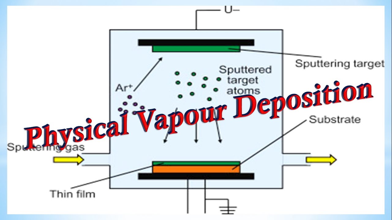
Physical Vapour Deposition - Detailed Explanation - YouTube

DEGASSERS Drilling Fluid Management & Disposal

Polymers | Free Full-Text | Versatile Polypropylene Copolymers from a

Lcms Diagram Degasser
Degasser systems are available in ASME and IEI Good Engineering Practices

Integrated degasser ? mechanical separator configuration | Download
